

Intersectionality is what life is about right?
Well it's here. The intersection of computers, nerds, Land Cruisers, general relativity, and ice cream. Just because. Ice cream is amazing. It has nothing to do with electronics, but it's delicious.
- Details
- Hits: 2163
Because Land Cruiser.
I put a computer controlled engine in my 1978 FJ40. Such a fun project. So it turns out that most car folks aren't computer folks, and outside of engineering, they're definitely not electronics folks. There are so many solutions out there for life's little problems, but so few solutions out there for vehicle speed sensors (henceforth "VSS"). <lecture> In case you're wondering, yes. you will need a VSS for the proper operation of of a computer controlled vehicle. Some people say no, but I am not one of those people. Don't take it out of the computer, don't disable the sensor, don't just put tape over the check engine light. You're better than that, and fuel emissions are so easy, stretch your brain. No cheating, it's not required. </lecture> Not all VSS' are created equal. I originally spent a ton on the Jags That run M22 4pulse sensor. It's a good solution, but mine was interfering with the parking brake cable and eventually broke. I took a moment to look at the sensor while it was open and it's a flywheel with 4 magnetic points on it that pass over a magnetic reed switch. Solid analog approach. I wish it were mounted inline with a flexible cable instead of a rigid aluminum housing. It appears at this time, the original M22 sensor is gone and there's an even more expensive reluctor wheel solution. For the price, TBI computers aren't really concerned about accuracy. Any fluctuating signal will do really. Get in the ballpark and it'll make do.
For MY Land Cruiser the problem I was faced with was a physically compatible sensor which was from a Mitsubishi Montero (Junkyard Score) or... Rock Auto - 1999 Montero Speed Sensor, being electronically incompatible with the engine computer. There's a path here... somewhere...

This sensor puts out an absurd, 32 pulses per rev and is a hall effect or optical type sensor. Totally fine, this will work...
Side note about these types of sensors... Since they're solid state passive (non generative) they do require some sort of power input. Generally they function in a range that includes 5v to 20v. This isn't always guaranteed, but I would bet that 5v is a good place to start.
...then we realize that the 1989 GM TBI computer requires a short to ground "sensor" with 4 pulses (shorts) per rev. No problem, what is a 12v to 5v power regulator that uses this weird hall effect sensor to ground out a transistor connected to the VSS input going to cost me? Well, nothing because it doesn't exist. Add in a circuit that divides pulses (binary) to get from 32 pulses down to 4, and we have been presented with an opportunity to learn some pretty simple electronics. Who doesn't want a stroll down PCB design lane to the corner of electrical engineering and computer engine control? I'm no fool, and definitely not scared of a little soldering iron...
Where to start?
Well I know I have to divide pulses, so this is binary logic essentially. one on/off cycle should equal a single on, then the next on/off cycle will equal an off... so on and so forth. It turns out (I wasn't aware of this at first) some smart people at Texas Instruments have made a 14-pin IC that does all of this magic with multiple divisors. so a 32 pulse signal can be reduced to 4 pulses... PERFECT! Here's the engineering sheet on this chip. It's called a binary counter...
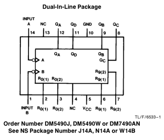
https://www.electroschematics.com/wp-content/uploads/2013/07/7493-datasheet.pdf
Here's a quick actual real breadboard POC of this IC. It's actually pretty awesome. https://www.facebook.com/lyppster/videos/10151608985473241/
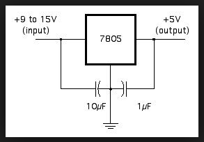
This chip, is powered by a 5v supply, so this is what I need to figure out how to provide from a filthy, 13.4v~ish battery/alternator. Turns out this is pretty dang easy. Whew knew!
A little research begins...
There are plenty of options, I'm sure they all have their pros and cons, they will all get the job done.
I chose autodesk's free online designer. https://circuits.io
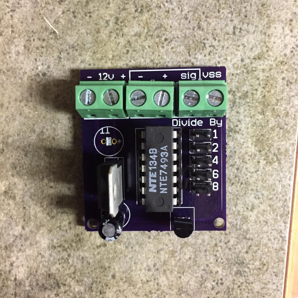
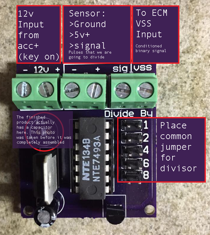
This application will help you design a circuit, breadboard it, design the PCB layout, AND generate the appropriate Gerber file layers to get the circuit boards manufactured. Totally awesome process. This circuit was simple enough for me to design, layout, and print correctly the 1st time. I decided that I would add a jumper system to adjust the output of the IC, and screw terminals for connectivity. (since I wasn't even sure this was going to work) One of the biggest challenges was to identify the right components to ensure all of it was going to fit. There's some black magic in here, but at the end of the day, it all worked out.
So rough overview of how the circuit works. we have a 12v+ & ground feeding a 7805 5v power regulator. this feeds electricity to power the 7493a binary counter IC and the sensor itself. The Montero sensor gets 5v+ from the regulator and ground, then generates a pulsed signal as the shaft rotates. This signal drives the 7805 IC appropriately. The divisor outputs from the IC are routed through a jumper to the PNP transistor which grounds out the VSS terminal (from the engine computer). Easy right? Right...
A little searching and I was able to find an affordable small batch-prototyping PCB manufacturer. I was able to upload the Gerber files that I created with circuits.io, and within a few weeks I had ready-made professionally manufactured printed circuit boards in my hand. This company keeps prices low by collecting enough designs to compile and print on large boards. As a result it can take a little longer to get your boards, but it's worth the wait. They look awesome.
https://oshpark.com for grins, I ran the Gerber file through this supplier and about $100 gets me 42 of these boards. minimum order was 3 boards for about $21. so totally doable price wise.
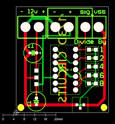
Gerber file for this specific PCB: Download
Feel free to download the above zip file and put it into the Gerber Viewer. This neat online tool helps you see the layers, turn them on & off to check your work before submitting it to the manufacturer.
This stuff is awesome. Nerds will inherit the Earth. It will be glorious.
I will put some photos of the finished product as it's installed here, and a parts list for the module, when I get an opportunity to compile that info. I think I actually have some boards left. I think I had to make a minimum of 6 boards. I've only used one, and it's perfect so far.
Interestingly, Marlin Crawler is producing this same physical sensor with the 4 pulse/rev signal. Decent price, you will still need to do some electronics magic to get it to work with a TBI computer. The TBI computer is still looking for a ground, not a weird binary (square wave) signal. You will have to provide it with 5v+, ground, then send the output to a PNP transistor inline with the VSS input (to the computer) wire which is expecting to be grounded 4x/rev. You still have to go to the junkyard to get a pigtail, might as well find a Montero and build a signal divider.
Ironically my 1980 FJ40 speedometer has a speed sensor in the speedo head that uses a magnetic reed switch, with probably a lot closer to 4 pulses/rev, it only worked for a minute before it died (probably because I was using it again after a bazillion years of being unplugged)
- Details
- Hits: 3783